

 Air Conditioner Systems (Electric Heat)
 Gas Split System
 Heat Pump Systems
 Mini Split Systems
 Package Units
 Mobile Home Systems
 AC & Heat Pump Condensers
 Evaporator Coils
 Air Handlers
 Electric Heat Kits
 Furnace
 Condenser Pad
 Drain Pans
 Fittings & Connections
 Flue Pipe
 Line Set
 Thermostat
 PVC Pipe & Fittings
 Miscellaneous Supplies
 Ducting & Venting
 Exhaust Fan
 Flex Duct
 Return Plenum
 Supply Plenum
 Registers & Grilles
 Filters
 Grilles
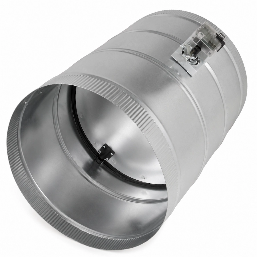

16” Motorized Damper – 24V Power Open/Close
$183.18

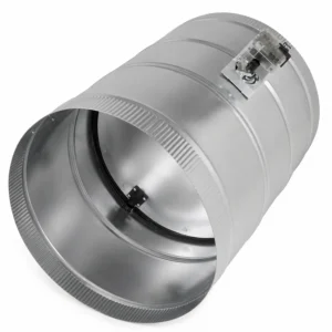
16 Inch Motorized Damper provides automatic airflow control for compatible HVAC zoning and ventilation systems. Its 24V motor powers the round damper blade in both directions, while red and green LEDs clearly indicate the fully closed or open position.
- 16-inch nominal round connection
- 24-volt motor operation
- Power-open and power-close design
- Single-leaf round damper
- Red LED indicates fully closed
- Green LED indicates fully open
- Three-wire electrical connection
Description
16 Inch Motorized Damper provides dependable, electrically operated airflow control for compatible HVAC zoning and ventilation systems. Its round, single-leaf design incorporates a 24-volt motor that actively moves the damper blade in both directions for powered opening and powered closing.
The damper also includes red and green LED indicators that display its fully closed or fully open position. The green indicator represents the open position, while the red indicator represents the closed position. These LEDs illuminate only after the blade reaches the corresponding end position.
16 Inch Motorized Damper Features
The 16 Inch Motorized Damper combines a large round duct connection with a two-position actuator. It is intended for systems that require electrical control of airflow through a compatible 16-inch duct branch or zone.
- 16-inch nominal round duct connection
- Single-leaf round damper design
- 24-volt motor operation
- Powered opening and powered closing
- Two controlled blade positions
- Red LED for the fully closed position
- Green LED for the fully open position
- LEDs activate only at the completed position
- Three-wire electrical connection
- Designed for compatible HVAC control systems
The three-wire connection includes one common wire, one powered-opening connection and one powered-closing connection. This configuration allows a compatible zoning panel, switch or HVAC controller to command the motor in either direction.
Motorized Airflow Control
The 16 Inch Motorized Damper controls airflow by rotating its internal blade between the open and closed positions. When the appropriate electrical connection is energized, the motor moves the blade toward the selected position.
Unlike a spring-return damper, this model uses motor power for both opening and closing. The controlling device must therefore provide the correct 24V signal through the appropriate wire for each direction.
When fully open, the damper allows air to move through the connected duct. When fully closed, it restricts airflow to the controlled branch. Actual leakage and pressure performance depend on the product design, installation and operating conditions.
This two-position design is intended for applications that require open-or-closed control. It should not be treated as a modulating damper unless the manufacturer specifically approves that type of operation.
LED Position Indicators
The integrated indicators help technicians confirm the operating position of the 16 Inch Motorized Damper. A green LED indicates that the blade has reached its fully open position, while a red LED indicates that it has reached its fully closed position.
The indicators are designed not to illuminate until the damper completes its commanded movement. This provides a clearer visual confirmation than an indicator that activates immediately when the motor receives power.
If neither LED illuminates after a command, inspect the 24V power supply, control signal, wiring and damper movement. Electrical troubleshooting should be completed by a qualified HVAC technician using the appropriate testing equipment.
HVAC Zoning Applications
The 16 Inch Motorized Damper can be incorporated into compatible forced-air zoning systems. In a zoned system, individual dampers regulate airflow to different areas according to thermostat demand and commands from the zoning control panel.
When a zone requires heating or cooling, its associated damper can open. When the zone is satisfied, the control system can command the damper to close. This operation helps direct conditioned air toward the zones that currently require it.
Closing duct branches changes the available airflow area and may increase static pressure. The entire zoning system must be designed to protect the HVAC equipment and maintain adequate airflow under all operating conditions.
A motorized damper alone does not create a complete zoning system. Compatible thermostats, a zoning panel, transformers, sensors and pressure-control components may also be required.
Installing the 16 Inch Motorized Damper
Before installing the 16 Inch Motorized Damper, confirm that the round duct connection and available installation space are suitable for the product. The actuator and wiring terminals should remain accessible for installation, testing and future maintenance.
Position the damper according to the permitted mounting orientation and intended direction of airflow. Avoid locations where the motor could contact framing, insulation, refrigerant piping or other building components.
Secure the duct connections using approved fasteners. Seal joints with HVAC-approved mastic, tape or another appropriate sealing method. Proper sealing helps prevent conditioned-air leakage around the damper body.
The adjoining ductwork should be supported independently. Excessive duct weight or misalignment can place unnecessary stress on the damper body and motor assembly.
Electrical Connection Requirements
The motor requires a compatible 24-volt control circuit. The three-wire arrangement consists of a common connection, a powered-opening wire and a powered-closing wire.
Verify the wiring terminals and control sequence before applying power. Connecting the wrong voltage or energizing incompatible terminals can damage the actuator or HVAC controls.
The transformer and control panel must have enough capacity for every connected damper and accessory. When multiple dampers operate simultaneously, their combined electrical demand must remain within the control system’s ratings.
All wiring should comply with the manufacturer’s instructions and applicable electrical codes. Disconnect power before making or changing electrical connections.
System Setup and Testing
After installation, command the 16 Inch Motorized Damper to open and close through the intended HVAC controller. Confirm that the blade travels smoothly to both positions and that the corresponding LED illuminates only after movement is complete.
Check the connected zone for proper airflow with the blade open. Verify that airflow is appropriately restricted when the blade closes. Also test the complete zoning system with different combinations of dampers open and closed.
Measure system static pressure and equipment airflow when required. If closing zones creates excessive pressure, the duct design, blower settings or pressure-control strategy may require adjustment.
Inspection and Maintenance
Inspect the damper during routine HVAC service. Check the electrical wiring, actuator mounting, duct seals and mechanical connections. The damper blade should move without binding or unusual noise.
Dust, damaged ductwork or physical obstructions can interfere with blade movement. Do not manually force the blade unless the manufacturer’s instructions specifically permit that procedure.
If a position LED does not match the actual blade position, discontinue automatic operation and have the control system inspected. The issue may involve wiring, voltage, motor travel or the internal position switch.
Professional Installation Recommended
The 16 Inch Motorized Damper should be installed by a qualified HVAC professional familiar with low-voltage wiring, zoning controls and airflow measurement. Improper installation can cause control problems, excessive static pressure or insufficient equipment airflow.
This product includes the motorized damper assembly only. Zoning panels, thermostats, transformers, ductwork, fasteners and sealing materials may be sold separately. Confirm compatibility before ordering.
Find additional compatible components in the Xpress Supply Ducting & Venting category. For official information regarding stationary air-conditioning systems and technician requirements, visit the EPA Section 608 refrigeration and air-conditioning resources.
About XSupply
Quality HVAC parts, air filters, replacement components, and installation supplies designed to deliver reliable performance, dependable compatibility, and exceptional value for residential and commercial HVAC systems.